In the modern architecture, engineering, and construction industry, BIM has completely transformed how projects are designed and managed. However, professionals frequently stumble over two crucial terms: level of development vs level of detail in BIM. While they sound remarkably similar, confusing them can lead to costly communication gaps, bloated file sizes, and budgeting errors. Level of detail focuses strictly on the visual and graphical sophistication of a 3D model, whereas level of development defines the accuracy and reliability of the data embedded within it. Understanding the precise boundary between these two concepts is essential for optimizing your BIM workflow, preventing over-modeling, and ensuring seamless collaboration across project phases.
This article breaks down the historical evolution of the LOD framework and explores how balancing graphics with data integrity protects your project’s timeline and bottom line.
The AEC industry’s horizon has witnessed many notable changes that have not only simplified the complex process but also resulted in the sector’s growth. The need for good infrastructure has always been a top priority for any architecture firm. As the sector’s innovation graph keeps getting higher, one of the best transformations of the wave came when BIM-building information modeling was introduced. BIM modeling services have and continue to revolutionize the sector with their long list of benefits and collaborative nature.
As vast as the AEC sector is, BIM modeling is also a wider concept to understand. It entails varied aspects that cater to the demands of the architecture process. As we all know, constructing any facility isn’t easy and requires the smallest of details to be accurately managed for desirable outcomes.
Build Your Next Project with Accurate BIM Services by Experts
Get a Quote
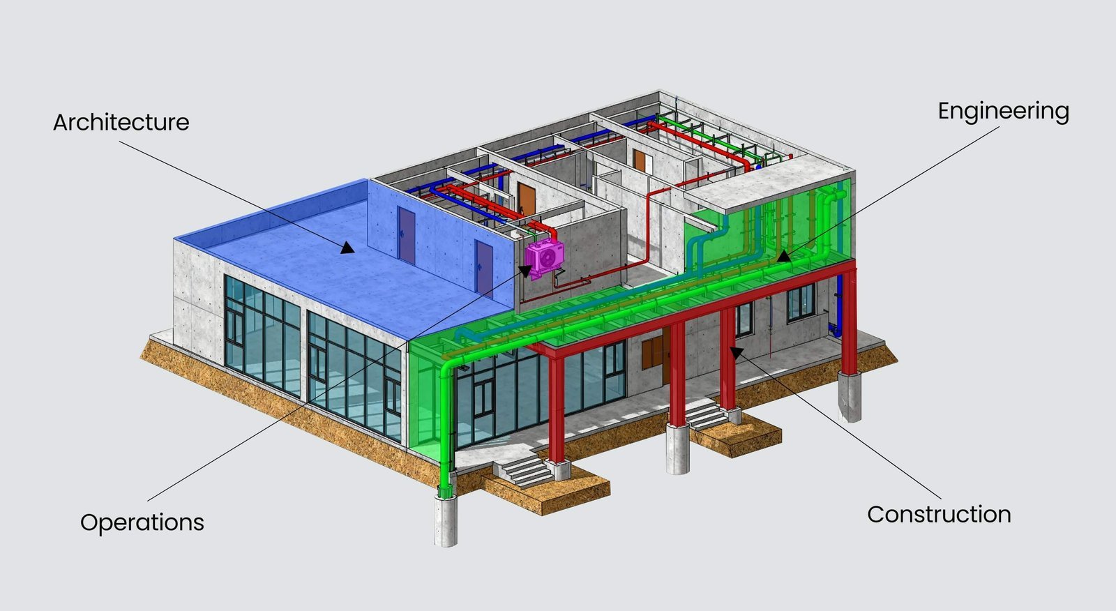
Moreover, today, we witness beautiful and unique architecture around us that catches our eye, although behind the beautiful exterior lies intricate detailing of every aspect. With the help of BIM services in the sector, architecture, engineers, and other collaborators can effectively execute the project with high precision.
Understanding each aspect of building information modeling within the BIM concept is essential. Out of many frameworks, understanding the concept of BIM level of development and BIM level of detail is essential. These two terminologies are interchangeable according to the requirement and carry great significance in the BIM concept. However, people usually confuse them, although they entail many differences. Let’s explore both concepts in detail, including the origin of LOD in the BIM concept.
The Origin of LOD
The history of LOD goes way back before it came into the sector’s spotlight. Although the framework of LOD was established by the American Institute of Architects (AIA) in 2008, it was further taken into the hands of Associated General Contractors of America (AGC).
What is the Level of Development?
In the process of construction and implementation of BIM, AEC professionals need to understand the level of completeness and how accurately the BIM model is incorporated at different phases of the construction process. Hence, the level of development defines the project completeness in the degree of reliability of the data entailed in the BIM 3D model. As a matter of fact, this offers transparency in communication and effective collaboration between the different professionals involved in the project.
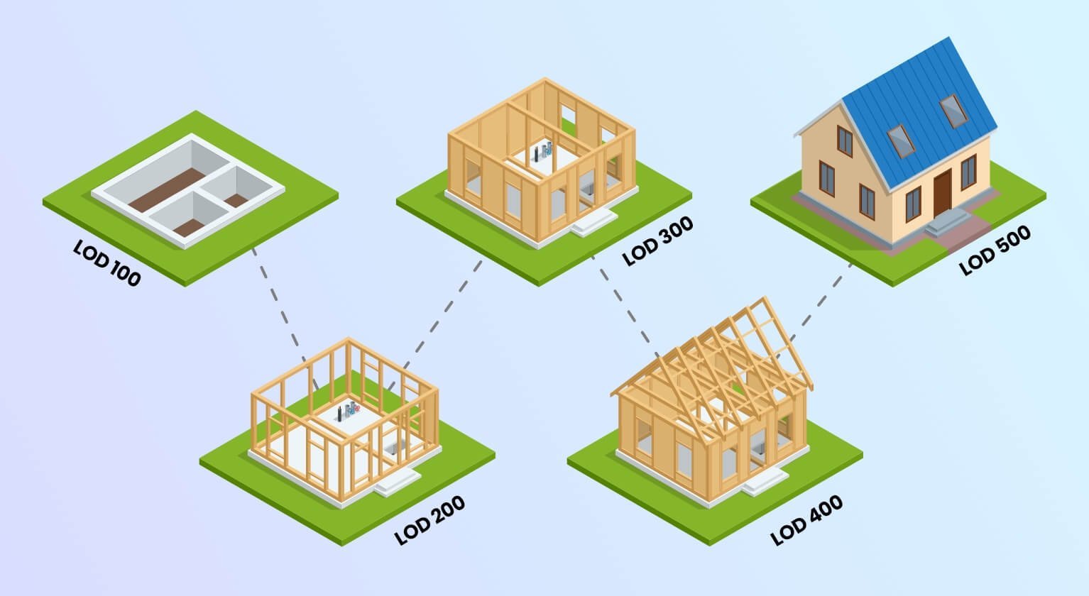
Furthermore, the BIM level of development acts as a key component in the entire construction process as it provides regulated and accurate management of the BIM model while the construction is completed. More than that, the level of development showcases and defines the amount of details incorporated in the BIM at different phases of the project. This explicitly fulfills the requirements and purpose of the BIM model. Usually, the BIM level of development, which caters to the level of completeness, ranges from LOD 100 – to LOD 500, with each level defining different stages.
- LOD 100- Concept Design
- LOD 200- Schematic Design
- LOD 300- Detailed Design
- LOD 400- Construction
- LOD 500- As-Built
What is the Level of Detailing?
As discussed, the BIM level of development describes the level of completeness. On the other hand, the BIM level of detail is defined as the amount of information and accuracy in the drawing. A higher level of detailing generally promotes bulk information incorporated in the drawings. Such information can include dimensions, notes and annotations, colors, textures, lighting, and more. The level of detail helps to provide accurate details, which are further used in the construction process. As a matter of fact, technical drawings serve different levels of detail, which may include;
- Sketch
- Concept Drawing
- Detailed Drawings
Level of Development Vs. Level of Detail and Their Applications
Both concepts hold significant importance in the BIM framework. The level of development and detail are usually interchangeable in the AEC industry, although both concepts of distance meanings and purpose serve in BIM projects.
The BIM Level of detail defines the amount of visual or graphical representation of information entailed in the BIM model. It caters to the amount of details added in the 3D BIM model, such as dimensions, textures, colors, and more. Typically, the BIM level of detail is used to define visual information in a particular phase of construction or the entire project.
On the other hand, the BIM level of development is described as the completeness and precision of the information input in the BIM model. This is further divided into five main types of levels, which showcase varied information and how far the construction is done. In fact, the level of development defines the degree of accuracy at different stages of the construction project, usually from conceptual design until the final phase of the construction is completed.
This is the major difference between these two concepts. Despite being interchangeable in the AEC sector, the application of BIM level of detail and development is incorporated in varied phases. The following are the significant applications;
Significant Applications of Level of Detail and Level of Development
Cost Estimating
Project Planning
Design and Coordination
- Cost Estimating:-Both LODs help prescribe the cost estimation for the entire construction project or each phase of the building, allowing for a better estimate of the quantity and reducing material wastage.
- Design and Coordination:- The level of detail and development are incorporated to ensure accuracy and reliability. Specifying each detail in the construction enables AEC professionals to avoid clashes, errors, and rework.
- Project Planning:- A rough estimate of the BIM project’s level of development and detail allows project managers to manage the timeline, resources, and budget accurately.
In a Nutshell
The significance of BIM’s level of detail and BIM’s level of development lies within their abilities. Each concept carries its own information, enabling project managers to accurately and efficiently complete the project and manage the operation, maintenance, and project lifecycle.